


TwistPort™ 101: Waveguide Technology Explained (Part 1/3)
What Exactly Is TwistPort™?
TwistPort is RF elements own proprietary waveguide-to-waveguide connector for connecting a waveguide ported radio with an antenna waveguide.
TwistPort™ is both:
-
an RF connector, and
-
a mechanical mount
between a radio and an antenna - all in one compact interface.
With a simple twist, the radio locks securely into place. Releasing it is just as simple. No tools, no screws, no fragile pigtails, no uncertainty. Because TwistPort is a waveguide, not a coaxial connector, it introduces virtually zero (practically extremely low) loss, making it the most efficient way to deliver RF energy from the radio to the antenna.
It is worth mentioning that TwistPort is useful when both sides - radio and the antenna - are waveguide ported by design. It means that the radio has a waveguide interface and the antenna utilizes a waveguide port, not a coaxial connector. The most obvious setup will include a travelling wave antenna (such as horn or parabolic reflector dish with a waveguide feed) rather than a resonator antenna.
We will first have a look at the RF properties of TwistPort to gain the understanding why it performs so well and what are all its advantages.
Waveguide
TwistPort is based on a waveguide - which is a structure that guides electromagnetic waves. It restricts the wave propagation to one dimension, making it an efficient tool for transfer of the radio waves from point A to point B. Waveguide is essentially an air-filled metal tube. Even the waveguide is a type of transmission line like any other cable, the difference is it only has one conductor - the hollow tube itself guides the harmonic signals, like the one shown on the bottom of the animation. The signal is called harmonic because of its shape.
Waveguides guide electromagnetic waves directly - without center conductors, dielectric losses, or cable-related inconsistencies.
As with anything RF, the waveguide size and frequency are related. Cutoff frequency of a wave guide is a frequency at which the RF signal starts to travel freely through the waveguide. If the frequency of the signal is lower than the cutoff frequency the wave fully reflects and nothing is traveling through the waveguide. As soon as the frequency of the feeding signal is higher than the cutoff, the wave can travel through the waveguide freely.
RF signal starts to travel freely through the waveguide at cutoff frequency.
The dimensions of the waveguide dictate what the cutoff frequency is going to be. In the case of a circular waveguide it is its diameter. When the size of the diameter increases the cutoff frequency decreases and vice versa - the smaller the waveguide diameter is, the higher the cutoff of the waveguide is.
The dimensions of the waveguide dictate the cutoff frequency,
We can calculate how the fields are distributed inside a waveguide. It all starts with Maxwell's famous equations, which describe how the electric and magnetic fields are created, and how they relate to each other. After some complicated math we get a solution to Maxwell's equations that describes the distribution of the fields inside the waveguide, and the conditions that have to be fulfilled for these fields to exist.
God is clearly a physicist
The fields inside a waveguide can be visualized in many ways, which helps us understand and analyze how the electromagnetic wave travels through the waveguide. Now in this example we show the electric field component. When we look at the fields in the waveguide cross section - or in other words - when we're looking from the front we call this field distribution a Mode. It is a pattern that is periodically repeated - the color of the field says how strong the fields are at each point.
Electric field distribution in a waveguide: Mode
We can also plot the magnetic field component separately. With circular waveguides, electric and magnetic fields look quite similar, but it is not the case with other types of wave guides. Also the mode of magnetic field looks quite similar to the electric one with the circular waveguide.
Magentic field distribution in a waveguide
At cutoff frequency the signal starts to travel in the waveguide, and its field only has one mode. So let's call that M1. This mode is well understood and we know how the waveguide behaves when it's operated in the first mode. The devices based on the waveguide operating in the mode M1 are also reliable and well
The first mode is called M1
As the frequency increases, additional cutoff frequencies are reached one after another. At each cutoff, a new propagation mode, distinct from the existing one, begins to propagate. These newly excited modes interact with the modes already present, and their superposition produces the field patterns you can see in the animation. Depending on the frequency of the feeding signal, multiple modes can exist in the waveguide at the same time, and they mix and create particular field distributions. Any mode above M1 is called higher-order mode, and besides creating different resulting field patterns, they also - we could say - suck the energy from the first mode, so the total energy of the RF signal is divided between all the existing modes. All the Higher-order modes are usually undesirable, because the waveguide based devices work reliably and predictably when only the first mode exists.
Useful bandwidth
Because of the unwanted Higher-order modes the useful bandwidth of a waveguide is limited. It's called a Single mode bandwidth and it is determined by two frequencies: first is the cutoff frequency fC over the first mode M1 at the lower frequency end, and second is the cutoff frequency fC 2 of the mode M2 at the higher frequency end. Because of the unpredictable behavior of higher order modes, for most practical applications the bandwidth of the waveguide is limited to these two frequencies, or between these two frequencies to be more precise. Both of these frequencies can be precisely calculated so it's quite easy to determine the Single mode bandwidth.
Higher order modes are not preferred because of their behavior
Waveguide Shapes
Waveguides can have various shapes as you can see from these sketches of waveguide cross sections. The most common are the rectangular ones, and circular. Each of the different shapes has certain advantages, like increased single-mode bandwidth, or power handling capability, but often at the expense of increased complexity and price.
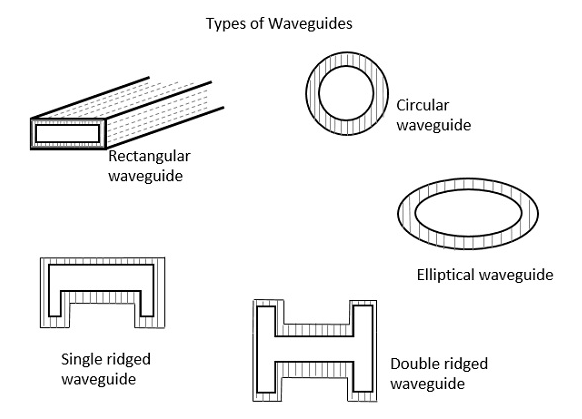
Examples of Waveguide Shapes (Picture courtesy of Dolph Microwave )
TwistPort is shaped around a circular waveguide. Circular waveguides are easier to connect than rectangular, easier to manufacture, have less loss, better power handling, and are structurally more rigid. They provide rotational symmetry. Adding ridges (single, dual, quadruple-ridged) to the waveguide provides multiple improvements. Ridge height influences higher order mode cut off, so it can provide very wide single-mode bandwidth. Ridges in the waveguide also help with impedance matching.
Because the waveguide is made of solid metal, the number of connecting and interconnecting parts have practical limitations. The shape of the waveguide is also practically limited as e.g. bends may introduce polarization shifts when not executed right.
Virtually Zero Loss
Compared to coaxial cable, the waveguide is practically lossless. Obviously, with extreme lengths there is a measurable loss / air attenuation, but compared to coaxial cable, we can reasonably consider waveguide a lossless tool for transfer of radio waves for short practical distances.
Let's talk about coaxial cable for a moment. Coaxial cable - or pigtail - is also a structure that guides electromagnetic waves. Now since this type of transmission line is the one that WISPs use the most often, it makes sense to do a little comparison of coaxial and waveguide technology.
Coaxial cable has two conductors, which introduces loss and other significant problems.
The main difference between coaxial cable and waveguide is that coaxial cable works from zero frequency - so it has no cutoff like the waveguide. It has two conductors - the center and the outer conductor, which fundamentally changes the way the transmission line behaves, including the loss introduced by the transmission line.
Here is a loss comparison of different types of coaxial cables and wave guides. The red lines represent different types of coaxial cable, and the black lines represent types of wave guides.
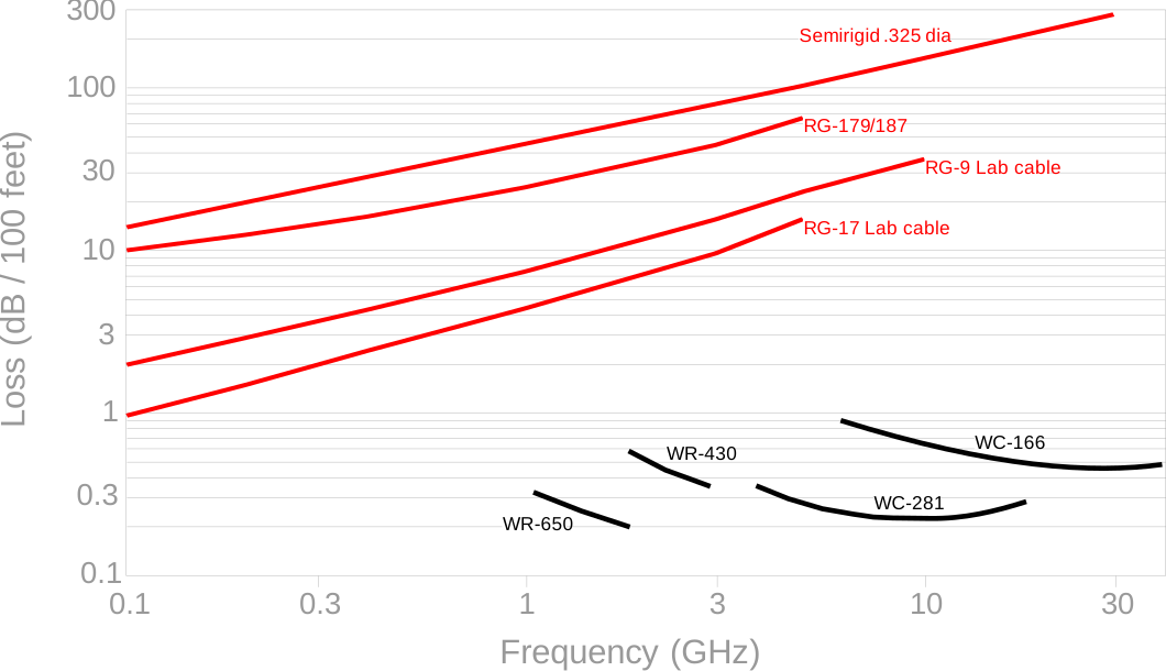
The waveguide has orders of magnitude smaller loss than coaxial cable.
The smallest loss of the coaxial cable starts somewhere at 1 dB per 100 feet, and that is at the lowest frequency of 0.1 GHz. So when we compare waveguide and coaxial cable at - let's say - 10 GHz frequency, it is obvious that there is a huge difference between the coaxial cable and waveguide. Overall we can tell that the waveguide has orders of magnitude smaller loss than coaxial cable. For example - looking at WC-281 at 10 GHz, it has approximately 0.2 dB per 100 feet loss, where the best coaxial cable has around 30 dB per 100 feet loss. So whenever you need an extremely low loss waveguide is simply a must.
Stay tuned for Part 2 to find out about mechanical design of TwistPort
reach out to you.
Hurray!
Thanks for your question. We will process it in the shortest time possible.
Subscribe to Our Newsletter
Latest news about wireless networking, our products and special offers straight to your inbox.