


Blog
Antenna Arrays
You use antennas and antenna arrays every single day whether you are aware of it, or not. Being a Wireless Internet Service Provider (WISP) even more so. A typical example of a WISP antenna array is the good old patch array sector antenna. But what are antenna arrays exactly?
In this blog you will learn about:
- What an antenna array is
- How antenna arrays work
- Examples of antenna arrays
The information here will help you understand why patch array antennas have side lobes that are hard to get rid of and what influences them.
What is an array antenna
Antenna array is typically a setup of two or more identical antennas working as one by being fed the same signal simultaneously.
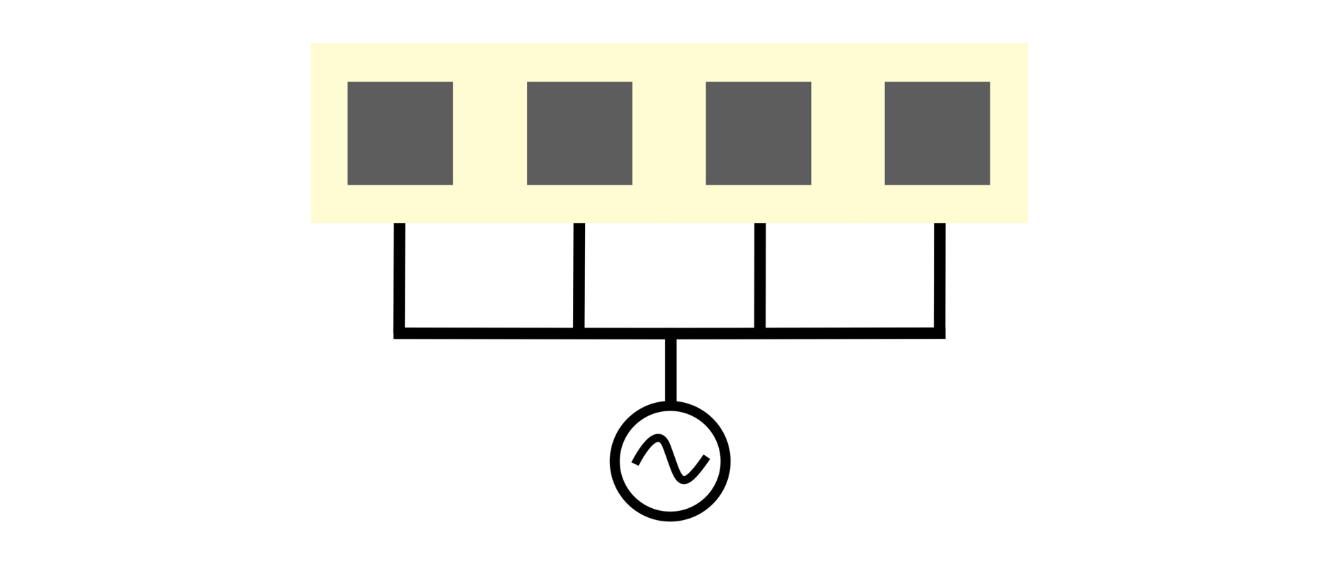
Schematic image of antenna array - identical antennas fed by the same signal simultaneously.
They are used in cases when the radiation pattern of a single element is too wide, if its gain is low, or if steering of the antenna radiation pattern is needed. Example of a single antenna radiation pattern is shown in the image below - it has low gain, fixed radiation pattern aiming, and wide beam width.
Radiation pattern of a single patch antenna with beam width of 120° and 7 dBi gain.
Any antenna can be used to form an antenna array. In practice, dipoles, patch or other circuit board printed antennas, horn antennas, or dish antennas are the most common examples of basic radiating elements used as array building blocks.
How antenna arrays work
The radiation properties of an antenna array can be explained through the physics of wave interference. Looking at the near field of a single patch antenna, we see how the waves leave the antenna and are radiated in space.
Near field of a single patch antenna.
Looking at the near field of two patch antennas fed by the same signal, it becomes clear why the radiation pattern of an array is so different compared to a single antenna. In directions where the waves add constructively are maxima of the radiation that results in a lobe in the far field pattern. In directions where the waves add destructively are minima of the radiation resulting in a null in the radiation pattern as shown in the image below.
Near field an array of two patch antennas after the waves from each patch add up - the maxima / minima explanation.
The far field radiation pattern corresponds to the fields seen in the near field. In directions where the waves interference is destructive, there is a null, and where the fields are strong - corresponding to constructive interference, there is a lobe.
Far field radiation pattern of an array of two patch antennas.
The principle of main lobe, side lobes, and nulls in the radiation pattern of an antenna array is the same regardless of the basic radiating element. Take a symmetrical horn antenna - it is possible it has a side lobe level below -30 dB. For applications in WISP networks, a horn like this can be considered an antenna with zero side lobes. This is because -30 dB means that any signal received outside the main lobe is thousand times weaker. For practical purposes, we can consider such an antenna having zero side lobes.
Making an array from these, or any other antenna, its radiation pattern has similar features - main lobe, side lobes stemming from constructive wave interference, and nulls stemming from destructive wave interference.
Radiation pattern of an array of horn antennas.
Another effect of forming an antenna array is higher resulting gain and decreasing beam width. The more antennas in an array, the higher the gain and narrower beam width. This is again due to the constructive interference of the waves radiating from multiple sources and the effect of physical size of an antenna on its gain.
Side lobes are an undesired result of wave interference and they get smaller with the increasing size of an array.
Effect of gradual increase of the number of antennas in an array on resulting radiation pattern and properties.
Array element spacing and arrangement shapes the radiation pattern. For example, beamwidth of the main lobe and the size and position of side lobes depend on the distance between the array elements. The further apart they are, the narrower the beamwidth due to growing total array size. Also the size and direction of side lobes change with element spacing because the fields add up differently for different antenna spacing.
Example of how the radiation pattern of an array changes with the element spacing change.
Examples of antenna arrays
There are three types of arrays - linear, surface, and conformal. Linear arrays are an arrangement of radiating elements in a line. These are well known in the WISP industry in the form of traditional patch array sector antennas. Looking at the array from the top, the shape of the radiation pattern copies the shape of the radiation pattern of a single patch antenna, while looking from the side, it follows the array physics described above.
Radiation pattern of a linear patch array antenna: side and top view.
Surface arrays have antennas arranged in a periodic pattern on a rectangular, circular, or other regular grid.
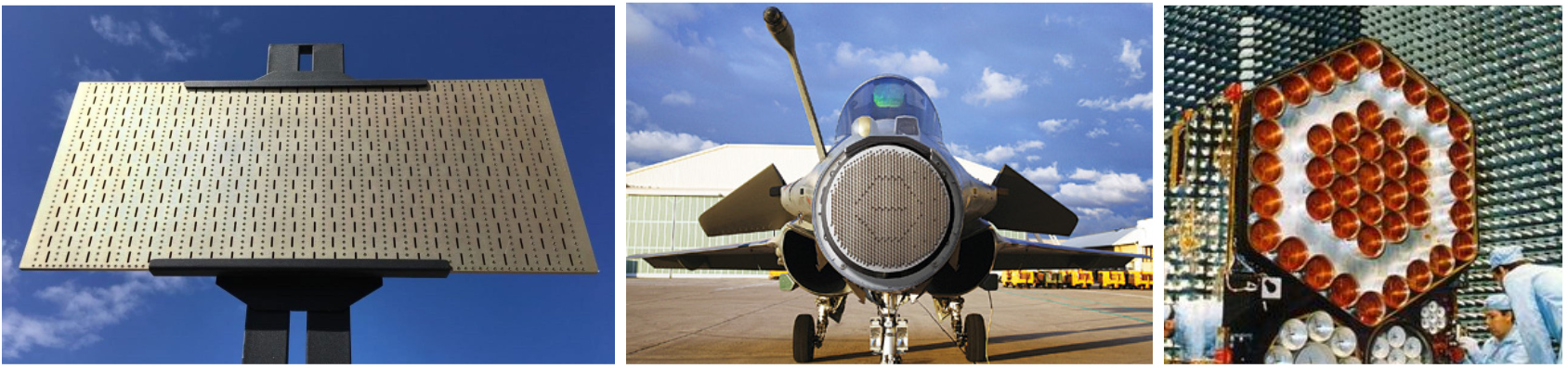
Examples of rectangular, circular, and hexagonal antenna arrays.
The radiation pattern of a surface array is directly proportional to the shape of the array. Below you see an example of a square patch array and its radiation pattern that is symmetrical - it has the same beamwidth in azimuth and elevation planes.
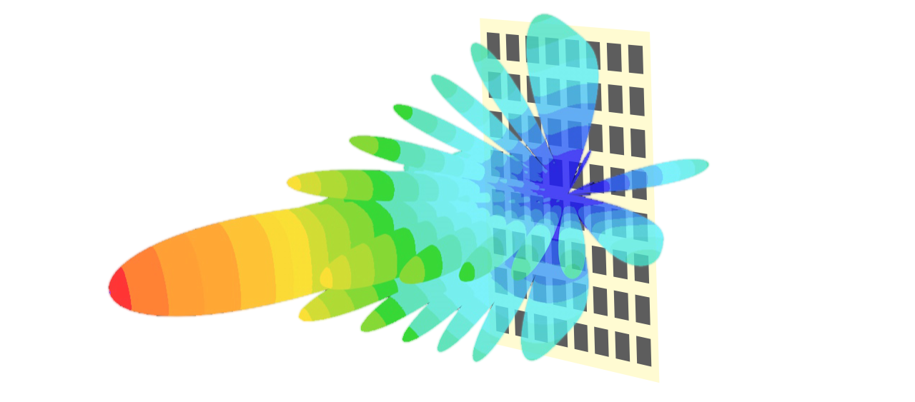
Square patch array antenna and its radiation pattern.
Sometimes it is necessary to fit an antenna array on a surface that is not flat. Antenna arrays that fit on curved surfaces are called conformal - see an example below including its radiation diagram provided each vertical set of patches has correct feeding signal phase resulting in a pattern with one main lobe.
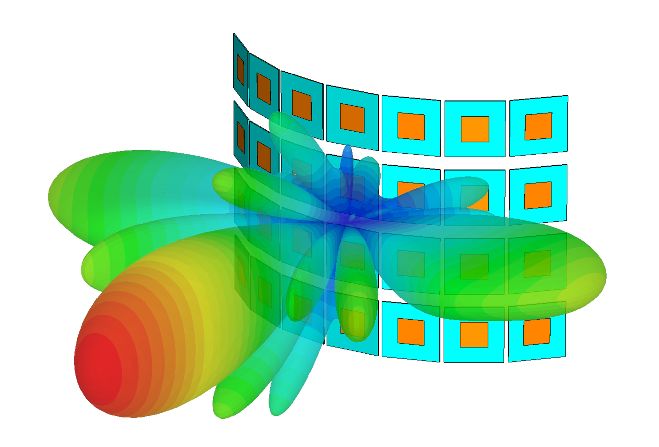
Example of conformal patch array antenna and its radiation pattern.
Conclusion
In many applications, antenna arrays make for an effective tool. Understanding the basics of antenna array physics, it is clear that the array parameters are more important than the individual element properties. The radiation properties are driven by the arrangement of the antennas and the feeding signals delay.
Many WISPs desire using horn antennas with radios capable of MU-MIMO hoping to leverage the noise rejection horns provide at the same time. Per antenna array physics we just learned about, even antenna arrays based on horns will have SLs in the resulting array radiation pattern. In fact, the MU-MIMO capability uses the side lobes to cover portions of the sector they are aimed at enabling grouping of the client stations. In that sense, the noise rejecting capability of horns is unused, since MU-MIMO relies on the side lobes for correct operation.
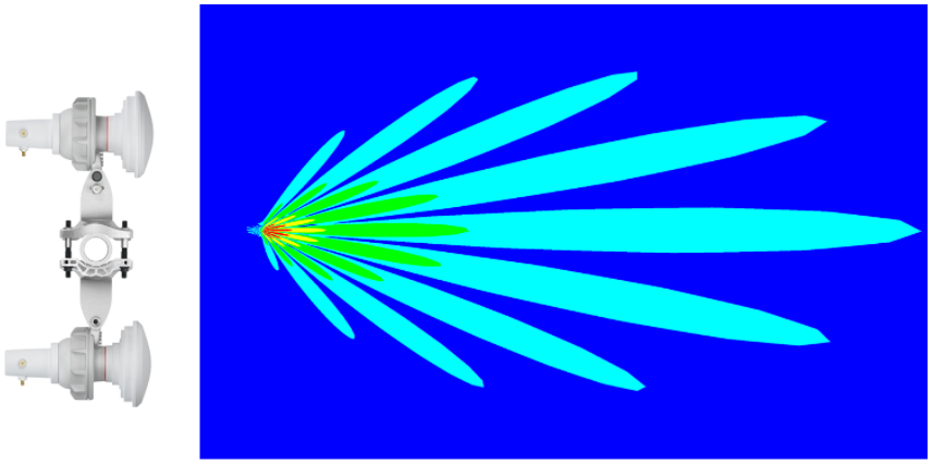
Coverage provided by an array of two horns aimed in the same direction and mounted on the same pole.
Here it is entirely up to the user to decide and test in the field which option works best for their particular scenario - whether MU-MIMO with arrayed horns or split / dense sector covered by two horns using 4x4 MIMO.
If you like the animated content better, check our Inside Wireless: Antenna Arrays video below.
reach out to you.
Hurray!
Thanks for your question. We will process it in the shortest time possible.
Subscribe to Our Newsletter
Latest news about wireless networking, our products and special offers straight to your inbox.