


Blog
Antenna Radiation Efficiency
Antenna Radiation Efficiency
Radiation efficiency is one of the basic antenna parameters you should know about. In this short post you will learn:
-
What is antenna radiation efficiency
-
What it depends on
-
How to calculate or measure it
-
How to utilize it in practice
Radiation efficiency (η) definition
Antenna radiation efficiency is closely tied to antenna gain and tells us what part of the RF signal energy delivered to the antenna is radiated into the free space. Here, the power delivered means the signal that made it through the feeding structure (typically cable, or waveguide) and has not reflected from the antenna input port.
Radiation efficiency spans values from 0 to 100 %, where 100 % is the ideal and it is an important part of the overall link budget equation. In reality, because of the material and manufacturing imperfections, we can only approach this value. There are three main components of the signal power loss decreasing antenna radiation efficiency.
The main cause of loss within an antenna structure itself varies depending on the antenna type - the full-metal antennas are affected mainly by the conductor loss, while with PCB based antennas the dielectric loss is dominant.
RADIATION EFFICIENCY LOSS COMPONENTS
Reflection Loss
The reflection loss is caused by the impedance mismatch of the antenna input port and the cable feeding it. The bigger the difference the more power is reflected from the antenna port decreasing the antenna radiation efficiency. Generally, circuit matching is a big part of RF engineering work - making various devices pass RF signals from one to the other effectively.
Conductor Loss
Electrical currents flowing through the metal antenna parts with particular resistance cause some of the RF signal power to be lost in the metal. In practice, it depends on antenna type, size, and operating frequency what the conductor loss will be but for most antennas, the conductor loss increases with frequency due to the increasing skin effect and at very high frequencies, higher surface roughness further amplifies the conductor loss.
Dielectric Loss
Materials such as PCB substrate on which antennas are often etched have so-called loss tangent, which is a measure of how strongly particular material absorbs the power of RF signal passing through it resulting in the material heating.
In practice, it is hard to compute or separate the conductor and dielectric loss but they can be determined experimentally. To determine the radiation efficiency, η, of an antenna, we can express the losses (L) as efficiencies. Efficiency is inversely proportional to the losses in a following way
η = 1 - L
It has values from 0 to 100 %, where 100 % would be the ideal value for each of them. Each loss component can be this way expressed as efficiency.
Radiation efficiency measurement and calculation
There are two ways antenna radiation efficiency can be determined. First, more frequented during the antenna design stage, is to calculate its radiation efficiency in an antenna modeling software. It is convenient, quick, and can be highly accurate if the antenna model corresponds to the real world sample.
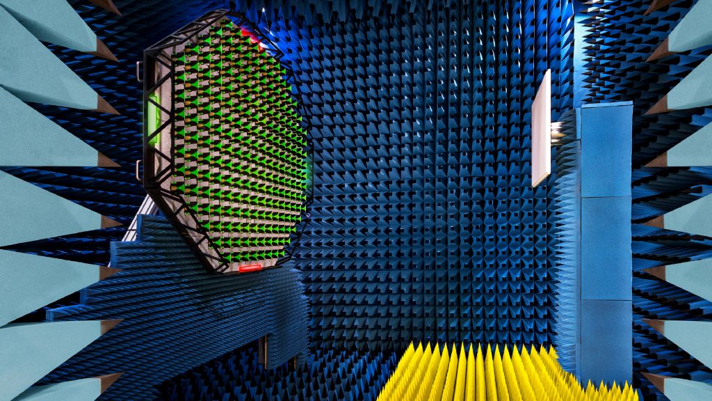
Second, considered the golden standard in the antenna industry, is experimental measurement. There are many options when it comes to antenna measurement setups depending on the frequency, size, and electrical size. Generally one can say that any RF measurements can be real-estate and hardware intensive. For example, an anechoic chamber can be the size of a warehouse and needs to comply with strict technical requirements quickly ramping up the total cost. On top of that, a custom rotary stage with measurement equipment accelerates the expenses growth even more. Nevertheless, these input costs are an inevitable part of precision antenna efficiency measurement.
Radiation efficiency in practice
Antenna radiation efficiency, η, that relates the absolute gain (G) and directivity (D) is defined as the product of the combined conductor and dielectric loss because these two components are tied to the materials an antenna is made of. This is the official definition of antenna efficiency according to IEEE Standards.
G = η ∙ D
η = ηCONDUCTOR & ηDIELECTRIC combined
Absolute gain, G, does not include losses arising from impedance mismatch, in other words, reflection loss, or polarization mismatch. Realized antenna gain, GR, includes the impedance mismatch on top of the materials losses and considers the chain of the feeding transmission line and the antenna together.
GR = ηR ∙ G
Ideally, antenna radiation efficiency would be 100 % meaning gain would be equal to directivity and all the power at the antenna ports is radiated into the free space and none is lost in the materials. But, since real-world materials always introduce some loss, we can only approach this value. The same goes for the realized gain - there is always some mismatch between a feeding cable and an antenna, so realized gain is always smaller than the absolute gain.
To share the content of this blog quickly, copy the link to our Inside Wireless video version below
reach out to you.
Hurray!
Thanks for your question. We will process it in the shortest time possible.
Subscribe to Our Newsletter
Latest news about wireless networking, our products and special offers straight to your inbox.