Blog
The Case for Asymmetrical Horns
RF elements'® Asymmetrical Horns are our most popular product series and they were awarded the WISPA Product of the Year in 2019. The Asymmetrical Horns have been on the market since the last year. Despite that, it might still be unclear to many how they fit into a WISP network. If questions about the Asymmetrical Horns, this blog is for you.
So first things first: what is the origin of the Asymmetrical Horns? It is simple, If you squeeze the Symmetrical horn from the sides, you get the Asymmetrical horns.
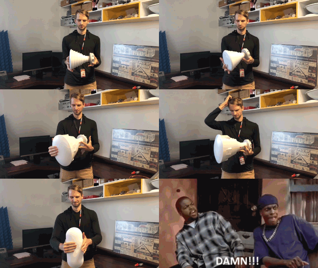
How Asymmetrical horns are made ;-)
Jokes aside, this is obviously an over-simplification. The truth is the design process took some time, blood, sweat, and tears. As a result of all that, we created a set of three antennas - HG3-TP-A20-30, HG3-TP-A60, and HG3-TP-A90. The 'squeeze' of the Asymmetrical Horn creates a higher gain and also causes the shape of the main beam to flatten compared to Symmetrical Horns with the same azimuth beamwidth. The gain of the Asymmetrical Horns is 20.5, 17, and 16 dBi; for 30°, 60°, and 90° beamwidths, respectively. All three the antennas work within 5180 - 6000 MHz bandwidth and the rest of the most important parameters are in the table below.
| Product ID | Gain (dBi) |
Azimuth beam width -6 dB |
Elevation beam width -6 dB |
| HG3-TP-A20-30 | 20.5 | H 30° / V 30° | H 20° / V 20° |
| HG3-TP-A60 | 17 | H 60° / V 60° | H 25° / V 25° |
| HG3-TP-A90 | 16 | H 90° / V 90° | H 25° / V 25° |
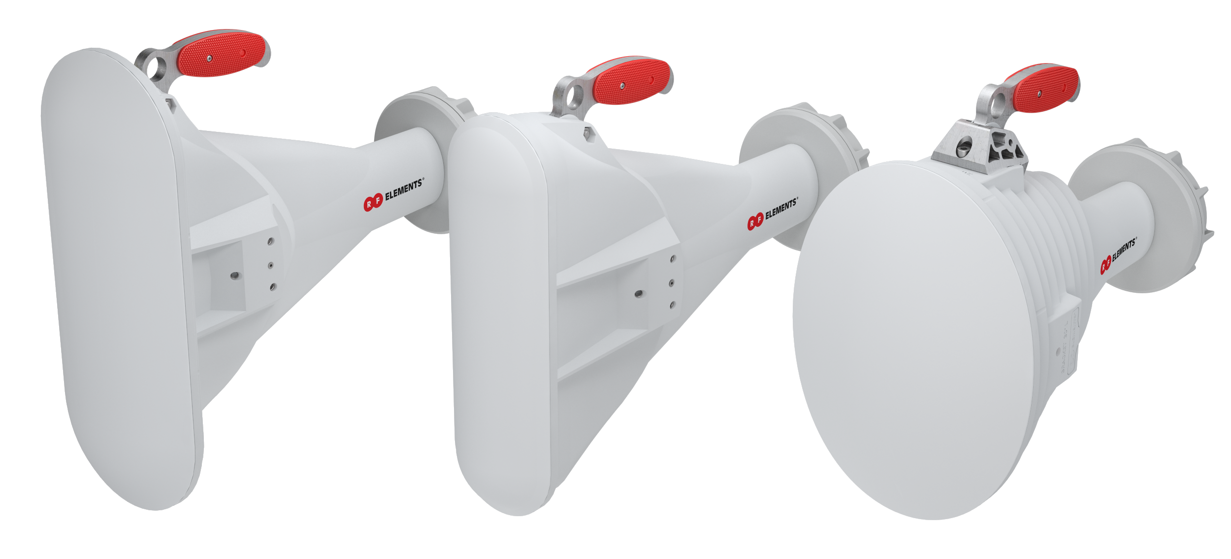
HG3-TP-A90, HG3-TP-A60, and HG3-TP-A20-30 Asymmetrical Horn antennas
The main beam of Asymmetrical Horns is wider in azimuth and narrower in the elevation. Let’s have a careful look at the antennas themselves: The Asymmetrical Horns come with three different Azimuth/Elevation beam widths for both Horizontal and Vertical polarization: 30°/20°, 60°/25°, and 90°/25°. On top of that, the BeamSwitch™ feature enables the user to rotate the 30° Asymmetrical Horn to obtain a radiation pattern with a beam width of 20°/30°.
The Azimuth & Elevation beam widths of Asymmetrical Horns
RF performance of Asymmetrical Horns
If designed well, horn antennas have excellent RF performance. In a WISP network, excellent performance means no sidelobes, great radiation efficiency, frequency stability of the radiation pattern, and sharp fall-off of radiation intensity.
Per the RF elements tradition, Asymmetrical Horns have one main beam and no sidelobes (sidenote for geeks - the sidelobe level is well below -30 dB). Asymmetrical Horn sectors transmit and receive signal only to and from the direction they are pointed at depending on the beam width, unlike a typical patch array sector. The vast majority of patch arrays for WISP networks receive noise from virtually all directions depending on the strength of sidelobes.
Comparison of a typical sector patch array radiating (and receiving) to all directions and Asymmetrical Horn with zero sidelobes and only one main beam
The additional received noise results in a higher noise floor. For a detailed explanation what noise floor is and why it is important, check our Inside Wireless video series. In short, higher noise floor means lower SNR (signal to noise ratio) the RF radio is working with. Smaller SNR causes lower achievable throughput and leaves the wireless network with sub-optimal performance, requiring constant attendance and service. On top of that, the end-users will also be unhappy with unreliable service.
The balanced performance of horns means that the radiation pattern of an antenna is the same for Horizontal and Vertical polarizations. Asymmetrical Horns are remarkably balanced, so switching chains on the radio will not cause any difference in the way the link performs, which is common with traditional flat sectors.
Balance between H and V polarization ensures great network stability when switching between the radio chains
The 30 degree Asymmetrical Horn has a BeamSwitch™ feature that lets you mount the antenna and physically rotated it by 90 degrees. As a result, the antenna has 20-degree azimuth beam width and 30-degree elevation beam width. BeamSwitch™ provides additional flexibility when planning your network coverage and lets you respond to changing situations with ease at no premium cost.
BeamSwitch™ feature of 30-degree Asymmetrical Horn lets you swap the azimuth and elevation beamwidths helping you stay flexible as the customer situation changes
Asymmetrical Horn antennas feature our proprietary waveguide connector TwistPort™. A waveguide is type of transmission line as coaxial cable is, but with completely different properties. The greatest advantage of a waveguide is near zero loss. This means 99.9% of the RF signal is delivered from a radio to an antenna. On the other hand, patch array antennas use coaxial connectors and pigtails, which can introduce as much as 3dB loss of signal power. 3dB means half (!) of the signal energy is lost in the cable. On top of that, coaxial cables wear out mechanically, are prone to damage by environmental elements, and deteriorate rather quickly.
TwistPort™ connector provides near zero loss and easy to use twist and lock radio mounting mechanism
Our TwistPort™ connector is optimized for easy, quick, and a durable connection. A simple twist and lock movement connects and mounts the radio at the same time. No need to attach the radio to the pole separately. For improved user experience, all TwistPort™ adaptors work with every TwistPort™ antenna we offer, so you never have to wonder whether you will need a new adaptor for a different TwistPort™ antenna.
Quick and simple installation of RF radios to TwistPort™ connector
Why Asymmetrical
Many WISPs think that Asymmetrical Horns are meant to replace the Symmetrical Horn series. That is not true, full stop! The conventional thinking that the newest products are mean to replace last year's model is a source of many problems in our industry and often confuses WISPs. Our approach is different from the mainstream. We are on a mission to build a complete system with high performance and unlimited scalability.
The Asymmetrical Horn series is best looked at as the new tool in the RF elements Horns toolbox. Imagine RF elements horn sectors (both Symmetrical and Asymmetrical) as a toolset, where each tool is suitable for a particular scenario. No longer you have to stick to the wide radiation angles of traditional patch array sectors with many frequency-dependent sidelobes that radiate uncontrollably in every direction transmitting and collecting noise.
WISPs still need Horns just as badly as in 2014, when we released the first generation of Symmetrical Horns. The main issues are interference, lack of spectrum, system loss, and scalability. RF elements' Horns enable WISP networks to scale, unlike the two or three types of patch array sectors currently on the market. The zero sidelobes combined with sharp radiation fall off let WISPs plan their network coverage in a highly granular manner. With horns, it is strikingly easy to collocate, scale, or even shrink (leveraging the mechanical tilt) the sectors.
Scalability is important for the sustainable growth of wireless networks. The industry standard patch array sectors with large sidelobes are the root of the noise problems. Interference makes your wireless network impossible in the long run. WISP networks can easily achieve scalability using horns instead of patch array sectors.
When to use Asymmetrical Horns
When should you use Asymmetrical Horns? It depends. A thorough way to approach RF projects is to consider each of them on a case by case basis and include as many details as possible. Any blanket statements should be taken with reservations since everything depends on frequency, bandwidth, and parameters of every part of a link. We will give you a few hints on where it might make sense to use the Asymmetrical horns and why.
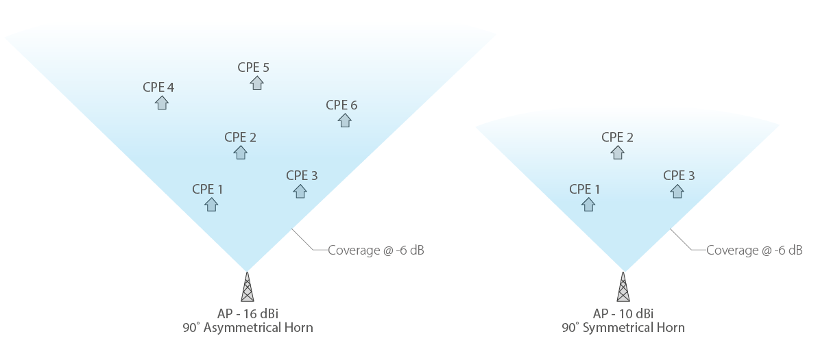
The Asymmetrical Horns are preferable when the customers are widely dispersed from the AP. Their higher gain is an advantage in this case. If the customers are only close to the AP, the Symmetrical Horns might be a better choice. The illustration below shows such a scenario. In densely populated urban environments with closely positioned CPEs, the lower gain Symmetrical Horns are a perfect fit as an AP antenna. In rural areas, with dispersed CPEs the Asymmetrical Horns works well - here the higher gain is welcome.
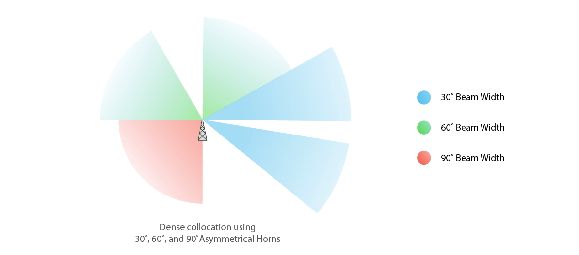
Staying with the rural scenario with dispersed customers, it is common that the only source of RF noise is your own antennas collocated on the same tower. The Asymmetrical Horns come to the rescue here as well. The zero sidelobes radiation pattern also means that the antennas are exceptionally easy to collocate. Shown in the image below is an example of how you can segment the sectors. You are free to cut the pizza any way you like, with a guarantee that the sectors will not interfere with each other. With this kind of setup, frequency reuse is effortless.
When speaking of gain and distance, the link budget is your best friend when designing any RF link. It is the equation used in the link calculator on our web page. All our antennas including the Asymmetrical Horns are integrated into the calculator. All you need to do is to select the antenna and other input parameters and you are ready to go. Check out how to use it for PTP and PTMP links in these short video tutorials. The link calculator will give you an approximate idea about much gain you need on both sides to achieve the MCS rate required.
And here comes a magic bullet:
“High gain on an access point antenna is generally not a good idea.”
Surprised? Yes, you read it right, the age-old wisdom of ‘higher gain equals better performance’ is one of the biggest myths among WISPs.
We understand adding more gain is a likable and easy idea to grasp idea - more gain equals better performance. However, this is only a part of the whole picture and has a definite limit in the real world. Most WISPs hit that limit very quickly! More gain on the AP side makes sense in situations when you are in a low interference environment. You should only use extra gain in cases where the link budget simply requires extra dBs to make it work - given there is no other parameter you can tweak. Even patch array sectors with plenty of sidelobes can perform decently in sparsely populated rural areas with almost zero noise sources. The sidelobes are not a big deal in clean environments where there is no noise to be collected in the first place. The high gain and wide beamwidth helps you reach customers wide and far away.
In suburban or urban areas, interference easily becomes a showstopper. Here, the high gain of the AP is a source of problems. You can decrease the output power to transmit the signal only as far as you need, but you can not change the coverage area when receiving because you cannot adjust the radiation pattern of an antenna.
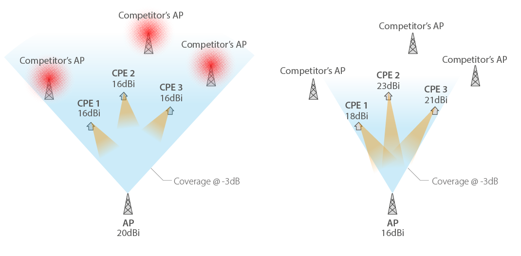
The correct solution for this situation is to use an AP antenna with smaller gain. In fact, as small as possible. You can compensate for the missing dBs on the AP side by increasing your CPE antenna gain.
On the left, a high gain and wide beamwidth antenna is used. Covering the CPEs as needed, but at the same time receiving the competitors’ APs noise. On the right side is an example of a better way to go about the noise vs. gain issue. Use lower gain and narrower beamwidth antenna on the AP side and higher gain antennas on the CPE side to achieve the desired performance. With a lower gain antenna, your competitor's APs are in the blind zone of your AP. This protects your AP from the excessive noise.
The landscape around your AP should also be taken into consideration. Symmetrical and Asymmetrical Horns perform well in flat or hilly regions. However, in real mountain regions such as the Sierra Nevada and similar, the wide range of Symmetrical Horns is the correct weapon of choice! When the shape of the radiation pattern and gain of the Symmetrical Horn series meets the requirements of the link, use them instead of Asymmetrical Horns. They are excellent for high-density deployments because they have a negligible null-zone and work wonderfully in all types of climates.

Asymmetrical Horns show their strength in places where the higher gain and their specific beam shape (compared to the Symmetrical Horn series or patch arrays) comes in handy. The asymmetrical shape of the radiation pattern works best in flat or mildly hilly landscapes. That means rural farmland areas with sweeping hills, urban or suburban areas with heavy interference and areas with lower customer density. There might be some difficulties covering wildly hilly or mountainous regions.


Actually, frequency stability is quite hard to achieve as soon as the radiation pattern becomes asymmetrical. It took a few years of effort to achieve the stability of the radiation pattern that our Asymmetrical horns have. The stability is important for uniform, dependable coverage and precise borders between the sectors. This is especially important for outstanding customer service and satisfaction.
Frequency stability of the radiation pattern of Asymmetrical Horns is superb and ensures coverage stability and precise borders between sectors.
Award-Winning Antennas!
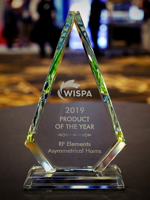
The RF performance of an antenna is critical and should always receive as few compromises as possible. Once the required performance is achieved, designers should lay their eyes at user experience from a mechanical point of view. The product should be durable, easy to assemble, transport, and mount. At RF elements we made no compromises and our customers have confirmed it for us. The Asymmetrical Horn antennas were elected the 2019 Product of the Year by WISPA members during the WISPAPalooza 2019 in Las Vegas, Nevada, USA.
At RF elements we think about products as a whole solution to a problem. Instead of providing customers with wannabe improvements such as ‘higher gain’, we look at every aspect of the product performance and we are not afraid to take bold steps into uncharted territory if we believe it is the best for the customer!
If you like video better than the written word, check out more features of the Asymmetrical Horns here:
reach out to you.
Hurray!
Thanks for your question. We will process it in the shortest time possible.
Subscribe to Our Newsletter
Latest news about wireless networking, our products and special offers straight to your inbox.
